So - we have a robot - actually we've had a robot for a while, but my blog writing hasn't caught up.
Meet Nanny McPi v1.0
This blog entry shows this initial build of Nanny, with a breakdown of the internals, and gives an idea of where we're going.
The Assembled Robot
The photos below show Nanny McPi fully assembled.
 |
| Top View |
 |
| Front View |
On top - there's not a lot at the moment except the main power switch and a couple of empty holes at the front we can use to attach the forklift for the tidy toys challenge. The front shape is supposed to represent a pair of eyebrows.
Looking from the front, you can see Nanny's nose - that houses the camera and ultra sonic sensor. These are the only sensors we're planning to use on the robot. We're planning to fit a plate across the top behind the nose where we can mount Nanny's eyes.
The camera is used to detect the coloured blocks in the tidy toys challenge and the target for the feed the fish challenge. We're also planning to use it to detect the sides of the arena and generate a horizon line. The angle of this horizon will give us an indication of how straight on we are to the wall, and we can correct accordingly. (In theory at least, we haven't tried this, although initial tests look promising).
The distance sensor is used to detect how far we are from the arena walls, coloured blocks, or the feed the fish target.
The wheels currently shown are not too large and not too grippy to give us good control for the arena challenges. We also have a set of larger 'off road' style wheels for the obstacle course.
Under The Hood
 |
| Under the Hood |
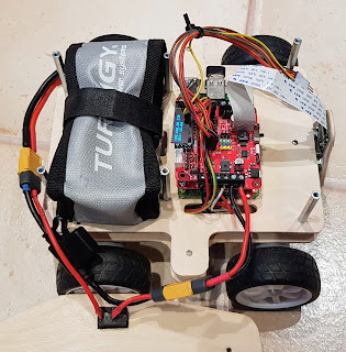
Taking off the lid, we can see most of the internals. For power we have a 3S LiPo battery. this is kept inside a fireproof pouch and protected with a 5A fuse and power switch before connecting to the motor controller.
The motor controller is a Red Robotics Redboard controller. (See https://redrobotics.co.uk/). This is a great board - as well as giving good motor control, it also provides power to the Raspberry Pi, and provides 3 pin connectors for each of the data pins so you have the 5v or 3.3v power pin and ground pin easily accessible. The small screen attached shows the Battery level and IP address. (Although I need to cut a hole in the roof to be able to see this in normal use). It does a lot more than this - so go to the link to check out all the features.
This sits on top of the Raspberry Pi - the model here is a Raspberry Pi 3 - although we'll be looking to upgrade to a Pi 4 at some point. The main reason we haven't upgraded yet is that I've already managed to kill one Raspberry Pi 4 with some dodgy soldering, so I'm sticking to a Pi 3 for now until I know the electronics are OK.
Coming out of the Pi you can see the camera cable, and also wires going into a dupont strip (Slightly hidden under the camera cable.) This is attached to the underside of the lid with velcro and allows us to attach the forklift, and other attachments, without removing the lid. Also attached are the wires for the ultrasonic sensor.
Also in the USB hub is a dongle for a Pi Hut controller. For Sputnik we used a playstation 3 controller. This was very reliable and the bluetooth pairing meant we didn't conflict with any other controllers.
However, since Pi Wars 2021 is set at home in a controlled environment, we've found the Pi Hut controller perfect - since there's no pairing involved - you just plug in the dongle and it works.
The Next Layer
 |
| The bottom layer with motor connector blocks |
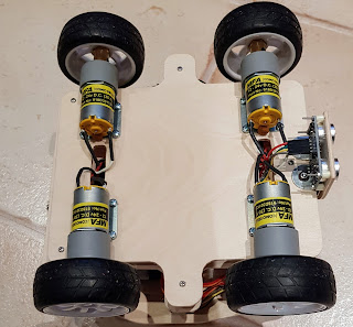
There's a narrow layer underneath the Raspberry Pi and Battery layer that is used for the motor mountings and terminal blocks used to join the motors together. Also in this layer is a small potential divider circuit used to bring the 5v output from the sonar sensor down to 3v to avoid damaging the Pi.
I'm planning on writing another blog entry soon to show how I connected the sonar sensor.
Currently nothing is bolted down - the terminal blocks are just big enough to fit inside this layer, so don't move about, and the wires on the circuit board keep it in place. I'll probably use some velcro to keep things in secure, and I'm also thinking of replacing the terminal blocks with some XT60 or XT30 connectors.
The Motors
 |
| Underneath |
No comments:
Post a Comment